+86-25-8470-5507

- All
- Product Name
- Product Keyword
- Product Model
- Product Summary
- Product Description
- Multi Field Search


Views: 0 Author: Site Editor Publish Time: 2026-06-24 Origin: Site


Selecting the right pumping equipment requires a delicate balance. You must carefully weigh static water levels against fluid viscosity. Environmental durability also plays a crucial role in your final choice. Every operation features unique demands. Deploying the wrong mechanism quickly leads to premature seal failure. It also causes inadequate flow rates or severe compliance risks. This becomes particularly dangerous in hazardous industrial environments.
Engineers and buyers need a reliable method to categorize these manual devices. We designed this article to provide a definitive evaluation framework. You will learn how to assess and shortlist equipment based on strict engineering realities. We cover everything from fundamental physics limitations to advanced material compatibility criteria. Our guide will help you navigate complex operational environments safely. You will discover exactly how to match the internal mechanism to your specific field requirements.
We must first ground our evaluation in fundamental physics. The core limitation of liquid transfer involves atmospheric pressure constraints. A theoretical suction limit exists at approximately 7 meters (or roughly 23 feet). Atmospheric pressure can only push water so high into a vacuum. You cannot cheat physics. If the water table sits below this depth, simple suction fails completely. You must utilize a different mechanical strategy.
Different application contexts demand vastly different evaluation criteria. Rural water supply systems require continuous, high-volume use. Operators need highly ergonomic designs to prevent physical fatigue during long shifts. Emergency backup systems prioritize intermittent reliability instead. They must function perfectly after sitting idle for many months. Conversely, industrial fluid transfer processes focus heavily on strict chemical compatibility. They prioritize safety over continuous high-volume output.
Misapplying equipment carries massive operational risks. Trying to pull fluids beyond physical limits causes immediate cavitation. This destructive phenomenon destroys internal components rapidly. Mismatched materials lead to accelerated seal wear. Contamination becomes a severe risk in these scenarios. We often see operators select cheap plastic units for solvent transfer. The solvents degrade the plastic housings. This action contaminates the fluid and permanently destroys the equipment. Proper specification eliminates these preventable failures.
Engineers categorize manual pumps based on their internal fluid displacement methods. Each design targets specific environmental parameters. Understanding these structural differences ensures successful field deployment.
These devices rely entirely on atmospheric pressure. A piston moves upward inside the cylinder. This movement creates a vacuum. Atmospheric pressure then pushes the fluid up the pipe to fill this void. The mechanism operates entirely above ground.
Engineers deploy these units for shallow water tables. They work exceptionally well for basic fluid transfer tasks. You will find them heavily used in residential gardens or small agricultural plots. They require minimal maintenance due to their accessible components.
However, inherent limitations exist. They absolutely cannot pull fluids from deep sources. They are also highly prone to losing prime. A tiny pinhole leak in the drop pipe stops the operation entirely.
Engineers design lift mechanisms for deep subterranean applications. The cylinder and valves sit completely below the water level. The operator pushes the handle down. This action physically lifts the submerged water column up the rising main. The famous India Mark II serves as a prime example.
These units excel at significant depths. They handle ranges from 15 meters to well over 45 meters. They provide reliable community water access in remote regions. They operate independently of atmospheric suction limits.
High installation complexity remains their biggest drawback. You need heavy lifting equipment to lower the heavy rising main. The handle operation also requires greater mechanical advantage. Users must exert more force to lift heavy water columns.
Force mechanisms share similarities with standard lift designs. However, they feature a completely sealed top section. This sealed housing captures the lifted fluid. It then forces the water above the pump outlet. It pushes fluid up into elevated storage tanks.
Planners use these units for pressurized systems. They serve elevated reservoirs perfectly. They allow users to pump water uphill over long distances.
The sealed design introduces new challenges. Higher internal pressure significantly increases wear on the upper seals. You must monitor these seals frequently. A blown seal eliminates the entire pressurization capability.
These specialized units use a flexible elastomer diaphragm. The handle moves the diaphragm back and forth. This action displaces the fluid effectively. The design completely avoids internal sliding friction. No metal parts grind against each other.
They handle difficult fluids flawlessly. Operators use them for abrasive slurries, muddy water, or high-particulate matter. They tolerate rocks and debris easily. The lack of internal sliding seals makes them incredibly resilient to grit.
They do feature specific limitations. They produce much lower pressure outputs. Furthermore, the diaphragm material remains subject to continuous mechanical fatigue. It will eventually tear after millions of flexes.
Selecting an Industrial Hand Pump requires a specialized procurement approach. Heavy-duty environments introduce hazardous chemicals and extreme pressures. You must shift your focus from simple flow volumes to strict regulatory compliance.
Hydraulic models serve highly specialized roles. Technicians use them for system calibration, lifting, or actuating heavy machinery. Evaluation metrics change entirely here. You must focus on maximum PSI or Bar ratings. Flow volume becomes a secondary concern. The device must hold massive pressures without micro-leaking.
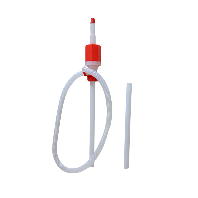
Rotary and lever barrel pumps dominate manufacturing floors. Designers build them specifically for dispensing oils, dangerous solvents, and volatile fuels. They mount directly onto standard 55-gallon drums. The rotary action provides a smooth, continuous flow. The lever action offers precise, measured dispensing.
Chemical and ATEX compliance remains non-negotiable in hazardous zones. Pumping volatile fuels requires non-sparking materials like bronze or specialized aluminum. You must utilize dedicated grounding wires to dissipate static electricity. Internal seals require specific chemical compounds. Standard rubber melts in harsh solvents. You must specify Viton or PTFE seals for corrosive fluids.
Construction materials dictate environmental survival. Evaluating material properties prevents catastrophic failures. Cast iron offers immense durability but remains incredibly heavy and rust-prone. Stainless steel provides unmatched corrosion resistance and hygienic properties for food-grade transfer. Engineered plastics offer lightweight, chemical-specific resistance but may shatter under blunt impact.
Procurement teams need structured methodologies. Choosing the ideal Hand Pump means systematically filtering out inappropriate designs. We provide a structured feature-to-outcome matrix below. It streamlines the complex technical evaluation process.
You must first determine the static water level or exact lift height. This remains the absolute non-negotiable first metric. Match your depth precisely to the certified operating range of the equipment. If you exceed the rated depth, the equipment will fail to deliver any fluid.
Next, calculate the required flow rate. Engineers call this the target yield. Assess the needed liters per minute (LPM). You can also evaluate strokes per liter. You must strictly factor in user fatigue for continuous operations. A high-yield unit might require excessive physical force. This renders it unusable for extended periods.
Always verify strict material compatibility. You must cross-reference the fluid pH, dynamic viscosity, and operating temperature. Compare these metrics against the wetted materials of the equipment. Wetted materials include any internal component touching the fluid.
Finally, assess the overall ergonomics and mechanical advantage. High-frequency usage scenarios require careful evaluation. Analyze the fulcrum design and the total handle length. A longer handle increases leverage. This ensures manageable user effort and prevents repetitive strain injuries.
| Evaluation Metric | Primary Consideration | Operational Outcome |
|---|---|---|
| Static Depth | Is the fluid below 7 meters? | Determines if suction or lift mechanism is mandatory. |
| Fluid Viscosity | Is the fluid thick like gear oil? | Dictates internal valve sizes and required leverage. |
| Fluid Abrasiveness | Does it contain sand or grit? | Forces selection of diaphragm mechanisms over pistons. |
| Chemical pH | Is it highly acidic or basic? | Dictates stainless steel or PTFE material selection. |
Theoretical performance often clashes with harsh implementation realities. Proper installation and rigorous maintenance determine long-term success. You must anticipate field vulnerabilities before finalizing your purchase.
Installation complexity varies wildly between categories. Surface-mounting a barrel unit takes less than five minutes. It requires no specialized tools. Conversely, deploying a deep-well cylinder requires extreme effort. You need heavy lifting tripods. You must ensure precise casing alignment. Even a slight angular misalignment causes the internal rods to rub. This quickly destroys the rising main.
You must identify wear parts and internal vulnerabilities immediately. Every mechanical device contains consumable components. Common failure points include leather suction cups, rubber O-rings, and heavy brass foot valves. You must establish a localized supply chain for these exact spares. A robust unit becomes useless if you cannot source a simple $2 replacement seal locally.
Winterization and environmental threats destroy unprepared equipment. Exposed cast-iron housings risk catastrophic freezing. Trapped water expands and shatters the heavy iron bodies. You must install proper drain-back valves for freezing climates. Furthermore, intense UV radiation severely degrades PVC components. You must protect plastic housings from direct sunlight to prevent brutal embrittlement.
Effective procurement logic follows a strict, sequential path. You must always start by measuring exact depths and analyzing fluid properties. You then filter available options by their core internal mechanism. Finally, you secure your investment by verifying material compatibility and confirming localized maintenance viability.
Never assume a one-size-fits-all solution exists. The most reliable equipment is the one matched perfectly to its specific operational environment. Ignoring basic physics or chemical realities guarantees premature failure.
A: A surface suction mechanism can only pull water from approximately 7 meters deep due to atmospheric pressure limits. However, submerged cylinder lift systems completely bypass this limit. They can physically lift water from depths exceeding 45 meters.
A: Lift mechanisms simply bring water up to the spout level for immediate collection. Force mechanisms feature a completely sealed top housing. This sealed design allows them to push water upwards into an external elevated tank.
A: You should never use them for drinking water unless explicitly certified. They often feature industrial-grade lubricants and non-hygienic seals. You must specify food-grade, non-toxic materials (like 316 stainless steel) to prevent severe cross-contamination.
A: Replacement timelines depend entirely on usage and fluid turbidity. High-frequency use with abrasive, sandy water may require seal replacements every six months. Clean water systems might operate flawlessly for up to three years before requiring new O-rings.


