+86-25-8470-5507


Views: 0 Author: Site Editor Publish Time: 2026-08-09 Origin: Site


Product giveaway, rejected batches, and line downtime cause compounding financial losses during manufacturing operations. Imprecise product transfer is often the primary culprit, even when facilities utilize high-end dosing mechanisms. A severe disconnect exists between theoretical pump or auger accuracy and actual container yield. Splashing, aeration, bridging, and overflow frequently occur at the final transfer point, which is the nozzle-to-container interface. This dynamic creates the "illusion of accuracy." A dosing pump might calibrate to a high nominal accuracy of ±0.5%. However, it can still produce out-of-tolerance final fills because of product hang-up and transfer loss during delivery. Engineered Funnels bridge this gap. Selecting the correct transfer geometry is never an afterthought. It serves as a primary driver of Overall Equipment Effectiveness and ensures strict volumetric compliance across all production runs.
Transfer Efficiency Dictates Yield: A highly accurate peristaltic or piston pump cannot overcome the volume loss caused by poor funnel geometry that induces splashing or product hang-up.
State-Specific Geometry: Liquid filling requires flow-control geometries to manage viscosity and prevent overflow, while solid/powder filling relies on steep discharge angles to prevent rat-holing and bridging.
Sanitary and Compliance Standards: Material selection (e.g., 316L stainless steel, FDA-approved polymers) directly impacts Clean-in-Place (CIP) turnaround times and cross-contamination risks.
System Integration: The most effective funnels operate in tandem with automated sensors and adaptive dosing algorithms to maintain real-time accuracy across diverse production runs.
Defining the success criteria for filling accuracy is the first step in optimizing any production line. Operations typically aim to maintain a ±1% target weight or volume tolerance while running at high throughput speeds. Achieving this metric requires perfect synchronization between the metering device and the final delivery mechanism. When a system fails to meet these tolerances, the root cause rarely lies within the pump itself. Instead, the failure occurs during the physical transfer of the product. The transition zone must handle the product gently yet swiftly to maintain cycle times. If you ignore the transfer path, you will constantly fight weight variations.
Funnels act as the transition zone in this process. They capture the exact dose from the metering device and direct it into restrictive container necks without loss. A poorly designed transfer path introduces friction, static electricity, and aerodynamic drag. These forces degrade the precision established by the volumetric or gravimetric feeder. The nominal yield represents what the machine dispenses, while the realized yield represents what actually enters the bottle. Bridging the doser-to-container gap requires precise engineering to ensure the realized yield matches the nominal yield perfectly. You need to account for every drop or granule that leaves the nozzle.
Analyzing the nominal versus realized yield gap reveals how transfer-path inefficiencies destroy accuracy. Fluid transport presents unique physical challenges compared to solid transport. Liquids introduce surface tension, aeration, and splashing into the equation. Solids introduce friction, compaction, and static cling. Each product state demands a specific approach to transfer geometry. If a liquid splashes out of the container, the volume is lost forever. If a powder clings to the sidewall, the container receives an underweight dose. Understanding these flow dynamics is essential for designing a system that delivers consistent results on the floor.
To properly evaluate the mechanics of your filling line, you must look at the entire fluid or powder pathway. Engineers often spend weeks calibrating a servo-driven auger only to watch the powder bridge in the final discharge spout. The same applies to liquid lines where high-speed piston pumps create violent fluid turbulence. The transfer geometry must act as a shock absorber and a guide. It takes the chaotic energy of the dispensed product and organizes it into a clean, predictable flow into the container.
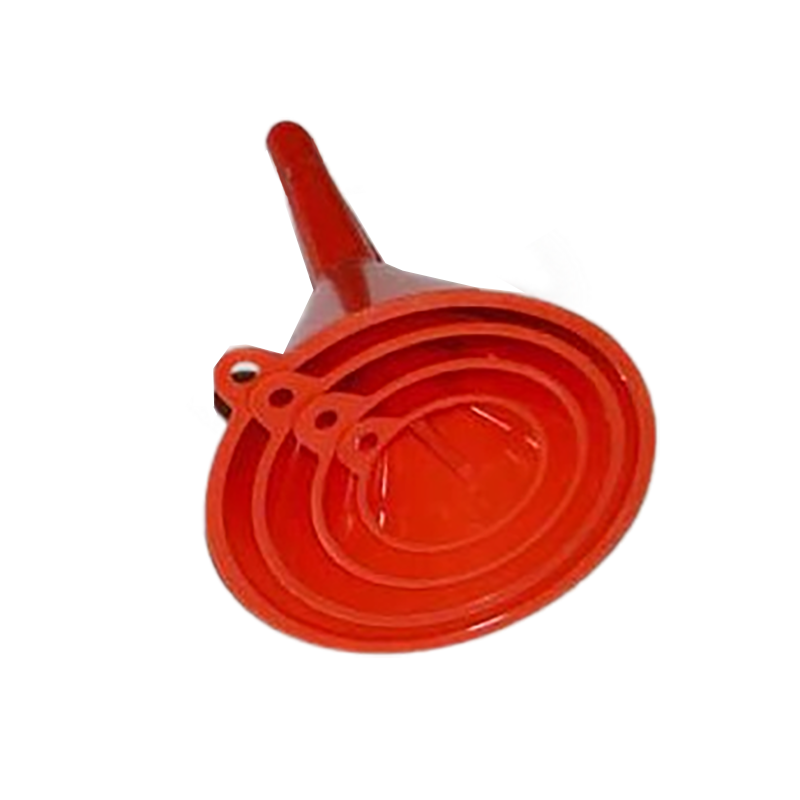
Different pumping technologies interact with transfer mechanisms in distinct ways. Piston technology relies on a high-velocity, pulsed discharge to move product. A positive displacement piston pump forcefully pushes a specific volume of liquid through the nozzle. A properly specified Filling Equipment Funnel manages this violent discharge to prevent turbulent backsplash. The geometry must absorb the kinetic energy of the fluid pulse. It then smooths the flow before the liquid enters the narrow container neck. Without this buffering effect, the liquid would violently hit the bottom of the bottle and eject upward, causing immediate volume loss.
Volumetric flow-meter integration presents a different set of challenges. Flow-based filling utilizes mass or magnetic meters to measure the exact amount of product passing through the line. The funnel plays a vital role in preserving the laminar flow profile necessary for these meters to function correctly. It translates high-precision meter readings into clean, dripless bottle entries. Any turbulence introduced at the transfer point can cause dripping after the fill cycle completes. Dripping not only creates a mess on the production line but also subtracts from the intended dose of the next container. You must maintain laminar flow to keep the line clean and accurate.
Peristaltic pump synchronization requires careful attention to flow stabilization. These pumps move liquids through flexible tubing, creating a continuous or slightly pulsed flow. Funnels act as stabilizing buffers for this delivery method. They mitigate the risk of micro-splattering when dispensing into small-neck pharmaceutical bottles. The transfer mechanism catches the liquid, allows it to pool slightly, and then guides it down the spout. This buffering action ensures that the fragile flow profile remains intact. It prevents the liquid from breaking apart into droplets that could adhere to the outside of the container neck.
When integrating these technologies, the physical distance between the pump discharge and the funnel opening matters. If the drop is too far, the liquid accelerates and creates splashing upon impact. If it is too close, backpressure can affect the pump's performance. Finding the optimal mounting height is a practical field adjustment that operators must dial in during commissioning. You have to watch the fluid behavior at full production speed to identify these micro-inefficiencies.
Controlling flow rates and preventing splashing are fundamental principles of gravity-assisted fluid transport. The physics of moving liquids dictate that you cannot force more volume through an opening than gravity allows. An essential operational rule is maintaining a maximum 3/4 capacity within the transfer zone. This practice allows liquids to flow without backing up or overflowing at the rim. When the liquid level exceeds this threshold, displaced air from the container cannot escape efficiently. The trapped air bubbles up through the liquid, causing violent splashing and immediate volume loss.
Managing fluid wetting and surface tension directly impacts transfer efficiency. The wetting properties of the fluid determine how it interacts with the inner walls of the delivery mechanism. Surface-tension dynamics can cause liquids to cling stubbornly to these surfaces. This clinging leads to cumulative volume loss over multiple cycles. It also causes delayed dripping, where a drop falls after the container has moved away. Engineers combat this by selecting materials and surface finishes that minimize surface energy. Reducing the friction between the liquid and the wall ensures a clean, rapid transfer.
Viscosity variances require adaptable design strategies. A single geometry cannot handle both thin, free-flowing aqueous solutions and thick, high-viscosity gels. Funnel design must adapt to specific liquid properties to maintain accuracy. You cannot use a water funnel for heavy motor oil and expect the same throughput.
Steep, narrow designs work best for free-flowing liquids to maintain velocity.
Wider geometries prevent bottlenecking when handling thick syrups or creams.
Heated jackets reduce the viscosity of temperature-sensitive products during transfer.
Pressurized enclosures force thick gels through the spout to maintain cycle times.
Anti-drip screens installed at the discharge point cut the fluid stream cleanly.
Temperature control is often overlooked in liquid filling. A product that flows easily at 80 degrees Fahrenheit might turn into a sluggish paste at 60 degrees. If your facility experiences temperature swings, your transfer geometry must account for the worst-case viscosity. Heated jackets or traced lines around the funnel body keep the product at a consistent temperature, ensuring the flow rate remains stable throughout the shift.
Solid and powder filling introduces the threat of rat-holing and bridging. Granular and powder flow mechanics are highly sensitive to friction and compaction. Rat-holing occurs when powder flows only through the center of the hopper, leaving stagnant material on the walls. Bridging happens when particles interlock to form an arch over the discharge orifice, completely stopping the flow. Specific funnel angles prevent these issues. Mass flow designs ensure all material moves simultaneously, while funnel flow designs allow center flow. Mass flow is generally preferred to prevent material compaction and ensure a consistent discharge rate.
Auger filler integration relies heavily on consistent material presentation. Auger dosing systems use a rotating screw to dispense a specific volume of powder per revolution. The funnel above the auger must maintain a consistent head pressure. If the head pressure fluctuates, the density of the powder entering the auger flights will vary. This variation destroys gravimetric and volumetric accuracy. The geometry must ensure a steady, uninterrupted supply of powder to the auger. It must prevent aeration or compaction that could alter the bulk density of the product before it reaches the container.
Dust control and product settling present significant challenges in solid filling environments. Airborne particulates represent lost product and a contaminated workspace. Enclosed or vacuum-assisted funnels capture this dust effectively. They ensure the entire metered dose reaches the container while maintaining a clean operating environment. Managing product settling is equally important. Powders often aerate during transfer, increasing their volume. The delivery mechanism must allow the powder to settle quickly inside the container. This prevents the product from overflowing before the container moves to the capping station.
Vibration is a common tool used to assist powder flow, but it must be applied correctly. Slapping a pneumatic vibrator onto a thin-walled funnel can actually cause fine powders to compact and bridge faster. Vibration should be tuned to the specific bulk density and particle size of the product. Sometimes, mechanical agitators inside the funnel are necessary to keep cohesive powders moving toward the discharge spout without packing them down.
Material compatibility and sanitary design are paramount, especially in regulated industries. Pharmaceutical and food-grade applications demand rigorous hygiene standards. 316L stainless steel is the industry standard due to its exceptional corrosion resistance and durability. Surface finishes play a critical role in performance. Electropolishing creates an ultra-smooth surface that reduces surface energy. Teflon coatings minimize wetting-fluid retention and eliminate product hang-up. These finishes ensure that every drop or grain of product leaves the transfer zone, maintaining strict dosing accuracy.
Geometry and discharge angles must match the specific container and product. The discharge diameter must align perfectly with the container opening. A common practice is sizing the nozzle slightly smaller than the neck. This clearance allows displaced air to escape without causing turbulence. Asymmetrical or eccentric shapes are often necessary for multi-lane filling machines. These designs allow multiple nozzles to fit closely together while still directing the product accurately into closely spaced containers.
| Product Type | Recommended Material | Ideal Geometry | Primary Challenge |
|---|---|---|---|
| Thin Liquids | Electropolished 316L | Steep angle, narrow spout | Splashing and dripping |
| Viscous Gels | Teflon-coated Stainless | Wide body, short spout | Product hang-up |
| Fine Powders | 316L Stainless Steel | Mass flow angle (>60°) | Bridging and dust |
| Granular Solids | Standard Stainless Steel | Funnel flow or Mass flow | Rat-holing |
Automation and sensor integration elevate the performance of modern transfer systems. Advanced setups integrate load cells and level sensors directly into the delivery path. Adaptive algorithms process real-time level and viscosity data. They use this information to adjust upstream pump speeds automatically. This closed-loop communication maintains a mean accuracy of up to 99.4% across diverse production runs. Sensors detect if the product is backing up and slow the pump to prevent overflow. This level of automation eliminates human error and guarantees consistent yields.
When evaluating a new setup, follow a strict validation process to ensure the geometry works for your specific application. Do not guess on the angles or the discharge diameter.
Measure the exact inner diameter of your smallest container neck.
Calculate the required flow rate to meet your target bottles-per-minute (BPM).
Test the product viscosity or bulk density at actual production temperatures.
Select a discharge spout diameter that allows 15% clearance for air displacement.
Run a 100-cycle test to measure standard deviation in fill weights.
Balancing throughput versus precision constraints is a constant operational challenge. Increasing line speed often degrades dosing accuracy. High speeds can easily overwhelm a funnel's discharge rate. When the pump delivers product faster than gravity can pull it through the spout, bottlenecking occurs. This leads to turbulent aeration, splashing, and inevitable overflow. Operators must find the optimal speed that maximizes output without compromising the ±1% tolerance limit. Pushing the equipment beyond its physical limits always results in unacceptable volume loss and rejected batches.
Changeover times and CIP compatibility significantly impact operational efficiency. Complex designs often increase downtime between product runs. Internal baffles, product splitters, or integrated screens for lump reduction complicate cleaning validation. These intricate components provide areas where product can hide, increasing the risk of cross-contamination. Evaluating the operational cost of these designs is necessary. A highly accurate but difficult-to-clean system may ultimately reduce overall line efficiency. Simple, streamlined geometries that support rapid CIP processes are generally preferred for multi-product facilities.
Environmental factors routinely disrupt transfer performance. Ambient humidity and temperature affect how products behave during delivery. In solid filling, high humidity causes powders to absorb moisture. This moisture makes the powder sticky, causing it to adhere to the walls and form bridges. In liquid filling, temperature drops increase the viscosity of the fluid. A liquid that flowed perfectly at 75 degrees may bottleneck and overflow at 65 degrees. Facilities must control their ambient environment or utilize heated and conditioned transfer mechanisms to mitigate these environmental risks.
Operator training is another implementation risk. If the line operators do not understand how to properly align the transfer mechanism with the container neck, you will experience constant spills. The equipment must be designed with positive stops and alignment pins so that it can only be installed one way after cleaning. Relying on visual alignment by the operator guarantees inconsistent performance across different shifts.
Dosing accuracy is only as reliable as the final delivery mechanism. An optimized transfer geometry is non-negotiable for achieving strict volumetric and gravimetric tolerances. Even the most advanced pumps will fail to deliver accurate yields if the product splashes, clings, or bridges at the final transition point. Overcoming the illusion of accuracy requires a comprehensive approach to fluid and solid dynamics.
Buyers must categorize their specific needs before selecting a geometry. You must evaluate the product state, viscosity, flowability, container neck size, and required throughput. Matching the physical properties of the product to the correct material and angle is the only way to guarantee performance. A mismatched system will always result in lost product and decreased efficiency.
Conduct flow-testing with actual product samples to observe real-world behavior.
Consult with a specialized tooling engineer to design custom discharge angles.
Request trial runs on your production line to validate OEE improvements.
Implement real-time sensors to monitor flow rates and prevent bottlenecking.
A: By ensuring 100% of the metered dose is transferred into the container without splashing, spilling, or hanging up on the equipment walls.
A: It is the assumption that high dosing accuracy at the pump or auger automatically translates to accurate container volumes, ignoring the product loss, splashing, and residue retention that occurs during the final transfer phase.
A: It depends on the powder's angle of repose, but generally, steep angles exceeding 60 degrees are required to achieve mass flow and prevent bridging.
A: They act as a stabilizing reservoir that catches the pulsed delivery from the flexible tubing, smoothing the flow before it enters the container.
A: Keeping the liquid level below 75% prevents the product from backing up, allowing displaced air from the container to escape without causing overflow at the rim.
A: Electropolished 316L stainless steel is the industry standard due to its corrosion resistance, ease of sterilization, and minimal product adherence.
A: Yes, funnels engineered with internal flow guides or angled spouts direct the liquid down the side of the container, minimizing turbulence and foaming.


