+86-25-8470-5507


Views: 0 Author: Site Editor Publish Time: 2026-08-03 Origin: Site


Determining how to select the right funnel size for your application is a critical operational challenge. Minor miscalculations in equipment dimensions often lead to severe bottlenecks, material bridging, overflow, and process contamination. When fluid dynamics, powder flow characteristics, and spatial constraints do not align with the correct geometric specifications, entire production lines can grind to a halt. A one-size-fits-all approach simply fails in high-stakes manufacturing, laboratory, or food processing environments.
To avoid these costly disruptions, you must adopt a systematic, engineering-based framework for evaluating application variables. By calculating required dimensions based on material properties, you can determine when off-the-shelf options suffice and when a specialized approach is necessary. This guide will walk you through the essential criteria for sizing Funnels accurately.
Flow Dynamics Dictate Geometry: The angle of the cone and the diameter of the spout must be precisely matched to the material's viscosity or angle of repose to prevent ratholing, bridging, and airlocks.
Capacity vs. Throughput: Top diameter determines surge capacity, while spout diameter strictly governs the maximum flow rate; both must align with batch processing speeds.
Surface Friction & Finishes: The internal surface roughness (Ra) of funnels directly impacts flow rates; a smoother finish reduces the required cone angle for cohesive solids and viscous liquids.
Standard vs. Specialized Needs: While standard sizes cover basic liquid transfers, abrasive, highly viscous, or sanitary applications often necessitate a custom funnel to meet exact compliance and integration standards.
Venting is Critical: Failing to account for air displacement in the receiving vessel is the leading cause of flow failure and hazardous splashing.
The primary operational goals of proper sizing include maximizing throughput, ensuring complete material discharge, and maintaining sanitary or safe transfer conditions. When equipment is incorrectly sized, the cost of failure is high. You risk downtime from clogs, material waste from spills, and safety hazards from chemical splashing or dust generation. In industrial settings, a stalled transfer process means lost production time and potential batch spoilage.
Before selecting equipment, establish baseline metrics. You need to know the target flow rate in gallons per minute or pounds per hour. Measure the receiving container dimensions and identify environmental constraints. Material characterization testing is also essential. Determine bulk density, dynamic viscosity, powder flowability using shear cell testing, and slip angle prior to sizing. Without these exact figures, any sizing attempt is merely a guess.
Consider the physical properties of the materials you handle daily. A fine, cohesive powder behaves entirely differently than a free-flowing granular solid. Similarly, a high-viscosity syrup requires a vastly different geometric profile than water or light solvents. Documenting these variables forms the foundation of your sizing strategy.
Identify the exact chemical composition and physical state of the material being transferred.
Measure the maximum allowable footprint and vertical clearance above the receiving vessel.
Calculate the required batch transfer time to maintain overall production line speed.
Conduct benchtop tests to determine the angle of repose for any dry bulk solids.
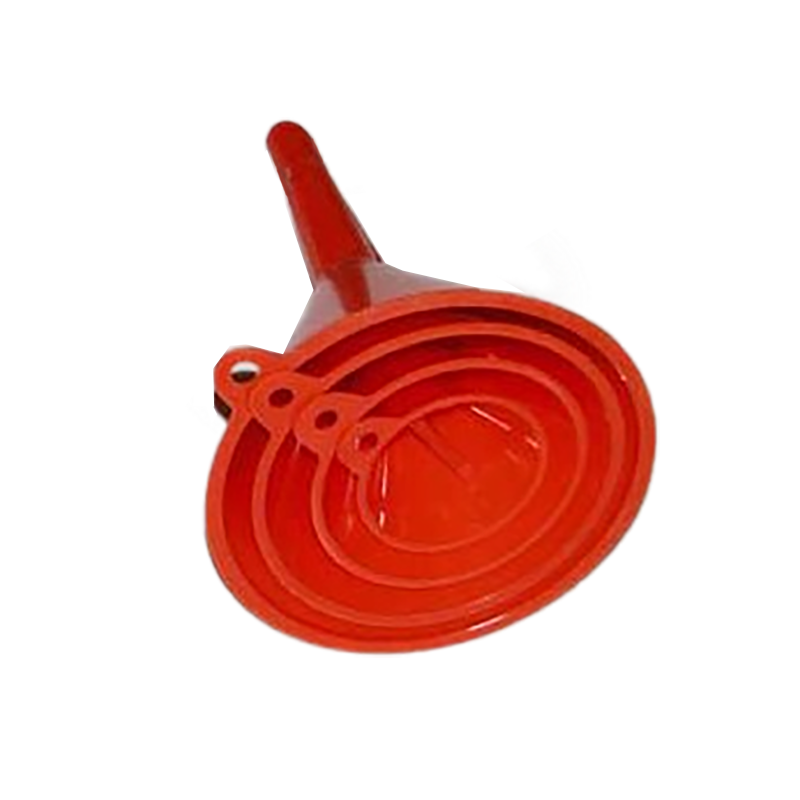
The top diameter dictates the surge capacity or catchment area. You must calculate the necessary volume to handle batch dumps without overflowing. The shape of the bowl—whether round, rectangular, or offset—also impacts the entry dynamics of the material. A wider top diameter allows for faster, less precise pouring without spillage, which is crucial during rapid batch processing.
When operators dump 50-pound bags of dry ingredients, the bowl must contain the initial surge before the material begins flowing through the spout. If the bowl is too small, material spills over the edges, creating waste and potential slip hazards. Calculate the maximum volume of your largest single dump and size the bowl to hold at least 125% of that volume to provide an adequate safety margin.
The spout diameter acts as the primary bottleneck governing maximum throughput. For liquid flow gravity discharge, use Bernoulli-based approximations to size the spout. For solid mass-flow limits, calculate the minimum outlet diameter required to prevent cohesive arching. Spout length also plays a functional role. Short spouts allow rapid discharge of thick materials, while long spouts provide directional control and minimize aeration in liquids.
A spout that is too narrow will choke the flow, regardless of how large the top bowl is. Conversely, a spout that is too wide may not fit into the receiving vessel or could cause the material to flow too quickly, leading to splashing or dust generation. The length of the spout must be sufficient to reach past the neck of the receiving container to prevent material from backing up around the outside of the stem.
The cone angle is critical for maintaining continuous flow. Steep angles are ideal for the mass flow of powders and high-viscosity liquids. Shallow angles may cause material to stall. Understand the angle of repose for bulk solids and the wall friction angle against stainless steel or plastic. The slope must exceed these parameters to prevent buildup and ensure complete discharge.
For highly cohesive materials, a 60-degree angle is often the minimum requirement, with 70 or even 80 degrees being necessary for particularly sticky substances. If the angle is too shallow, you will experience funnel flow, where a central channel empties out while material remains stagnant along the walls. This leads to ratholing and requires manual intervention to clear.
Liquids and solids behave differently. For liquids, specific gravity, surface tension, and the risk of vortexing impact the design. You must size the equipment to prevent vortex formation, which introduces air into the system. For dry materials, bridging, arching, and ratholing are major risks. Sizing must account for particle size distribution and moisture content to ensure reliable flow.
When handling liquids, the primary concern is achieving a smooth, laminar flow. Turbulence can cause foaming, which is highly undesirable in food and beverage or chemical applications. For powders, the focus shifts to overcoming friction and cohesion. Moisture content is a massive variable here; a powder that flows freely at 10% humidity may turn into a solid block at 50% humidity.
| Material Type | Primary Flow Risk | Recommended Geometric Feature |
|---|---|---|
| Low-Viscosity Liquid | Vortexing / Aeration | Longer spout, anti-vortex baffles |
| High-Viscosity Liquid | Slow discharge / Stalling | Short, wide spout; steep cone angle |
| Free-Flowing Powder | Dust generation | Covered top, extended spout reach |
| Cohesive Powder | Bridging / Ratholing | Extremely steep angle (>70°), oversized spout |
Dynamic viscosity often changes with temperature, altering the required spout diameter. A fluid that flows easily at room temperature may become sluggish in a cold environment. Always size based on the material's thickest state during the process cycle. This worst-case scenario planning prevents unexpected bottlenecks during temperature drops.
If your facility experiences significant seasonal temperature variations, you must account for this in your sizing calculations. A heavy oil might require a 1-inch spout in the summer but a 2-inch spout in the winter to maintain the same flow rate. In some cases, integrating heating jackets into the design is necessary to maintain a consistent viscosity year-round.
Matching the outer diameter of the spout to the inner diameter of the receiving receptacle is necessary for a clean transfer. You must evaluate clearance requirements and venting gaps. Stable, secure mounting interfaces are vital to prevent tipping or misalignment during operation.
Never assume a spout will fit simply because the nominal dimensions match. Manufacturing tolerances, weld seams, and container lip designs can all interfere with a proper fit. Always measure the actual internal diameter of the receiving vessel and ensure the spout outer diameter is at least 1/8 inch smaller to allow for easy insertion and removal.
Standard geometries, such as 60-degree cones and standard fractional spout sizes, are sufficient for many applications. Use them for low-viscosity fluids, non-hazardous environments, and standard drum filling. Off-the-shelf options offer significant cost and lead-time advantages when your process parameters fall within typical ranges.
If you are transferring water, light oils, or free-flowing granular materials like dry sand or grain, standard equipment will likely perform perfectly well. There is no need to over-engineer a solution for a simple problem. Standard sizes are readily available, easy to replace, and require no specialized design work.
Complex applications often trigger the need for custom engineering. Non-standard flow rates, unique spatial footprints, specialized mounting flanges, or extreme material properties require a tailored approach. The design process for a Custom Funnel involves CAD modeling, flow simulation, and prototyping. You can integrate custom features like internal baffles, offset spouts, heated jackets, or specialized venting tubes. Structural options like integrated Tri-Clamp, ANSI flange, or threaded fittings ensure leak-free closed transfers.
When dealing with highly reactive chemicals, ultra-pure pharmaceuticals, or extremely abrasive slurries, standard options will fail rapidly. Custom engineering allows you to specify exact material grades, precise surface finishes, and specific mounting hardware that integrates seamlessly with your existing infrastructure. This level of control is mandatory in heavily regulated industries.
Chemical compatibility is a primary concern. Evaluate stainless steel grades, high-density polyethylene, PTFE, and specialized alloys against corrosive materials. The internal surface finish affects material drag and sanitation. A mirror polish or electropolished finish reduces friction and aids cleaning. Regulatory compliance for FDA, USDA, 3-A, or cGMP standards often requires specific minimum radii on internal welds. Finally, address static buildup in powder transfer by specifying conductive materials, grounding lugs, or anti-static additives.
Using the wrong material can lead to catastrophic failure. A corrosive acid will quickly eat through standard 304 stainless steel, requiring an upgrade to 316L or a specialized fluoropolymer coating. In food processing, any surface imperfection can harbor bacteria, making strict adherence to sanitary design standards non-negotiable. Welds must be ground smooth and polished to eliminate crevices.
| Material | Best Application | Limitations |
|---|---|---|
| 304 Stainless Steel | General industrial, mild chemicals | Susceptible to chloride corrosion |
| 316L Stainless Steel | Pharmaceutical, food grade, harsh chemicals | Higher initial material cost |
| HDPE Plastic | Lightweight transfer, non-abrasive liquids | Low temperature tolerance, degrades in UV |
| PTFE Coated | Extremely sticky or highly corrosive materials | Coating can scratch or wear over time |
An improperly sized spout that perfectly seals the receiving container prevents air displacement. This creates an airlock, halting flow completely. To mitigate this, specify fluted spouts, external vent pipes, or utilize a custom design with integrated air-return channels.
Airlocks are incredibly common and often misdiagnosed as clogs. If you pour liquid into a bottle and it suddenly stops, burps, and splashes back, you have an airlock. The air inside the bottle must have a clear path to escape as the liquid enters. Designing a spout with exterior ribs or a dedicated vent tube solves this issue permanently.
The physical weight of fully loaded equipment can be substantial in large-scale industrial setups. Do not rely on the spout or the receiving vessel for load-bearing. Design appropriate structural supports, load-bearing tri-clamp fittings, or welded support brackets to ensure stability and safety.
A large stainless steel bowl filled with 100 pounds of dense powder exerts massive force on the spout. If the spout is resting on the thin neck of a plastic drum, the drum will collapse. Always engineer independent support structures, such as wall-mounted brackets or floor stands, to bear the weight of the equipment and the material.
Testing flow characteristics prior to full production is crucial. Implement benchtop drop-testing, sliding angle validation, and mock-up fits. Physical validation confirms that the calculated dimensions perform as expected under real-world conditions.
Never skip the testing phase. Build a cheap prototype out of cardboard or 3D print a scale model to verify the cone angle and spout diameter. Run a small batch of your actual material through the prototype. This inexpensive step can save thousands of dollars in rework by catching design flaws before you fabricate the final metal or heavy-duty plastic version.
Calculate your required throughput and batch times to determine the necessary spout diameter and bowl capacity.
Measure the exact internal dimensions of your receiving vessels to ensure proper spout clearance and venting.
Conduct benchtop flow tests on your materials to identify the correct cone angle and surface finish requirements.
Consult with a specialized manufacturer to draft a specification sheet if your process demands custom engineering.
A: Determine the total volume or mass of material you need to transfer and divide it by the required batch time. Match this rate against the discharge capacity of the spout diameter using fluid dynamics or mass flow calculations.
A: The best angle depends on the powder's angle of repose and wall friction. Generally, steep angles of 60 degrees or more are required to ensure mass flow and prevent bridging or ratholing in cohesive powders.
A: This is usually caused by an airlock. If the spout seals the opening of the receiving container, air cannot escape as liquid enters, creating pressure that stops the flow. Venting is required.
A: Upgrade when dealing with highly viscous materials, cohesive powders, strict sanitary requirements, unique mounting constraints, or when standard sizes fail to meet your required throughput without overflowing.
A: Sufficient clearance is needed to allow displaced air to escape. If a tight seal is required, you must incorporate a separate venting mechanism or use a fluted spout to prevent airlocks.


